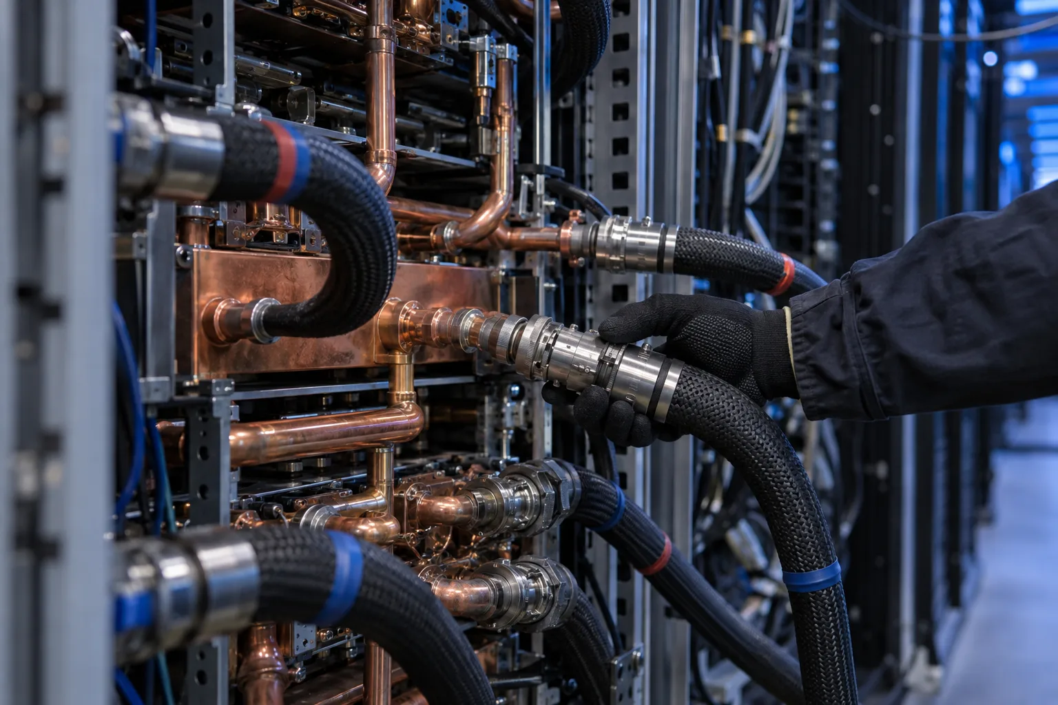
Corrosion inside a direct-to-chip cooling loop is slow and quiet. Copper leaves the cold plates, brass fittings lose zinc, and the products of both circulate through the cold plate channels. By the time a leak or a thermal alarm reports it, the fluid has usually been changing for some time. This guide covers which metals are at risk in a technology cooling system (TCS), the corrosion limits the industry uses, and how online corrosion measurement fits alongside coupons and lab analysis.
The source for the limits and methods is the Open Compute Project’s PG25 guidelines (version 1.0.0, September 2026), which cover inhibited propylene glycol fluids in liquid-cooled racks.
Why closed glycol loops still corrode
A sealed loop with inhibited coolant is designed not to corrode, and while the inhibitor package is intact it mostly does not. The guidelines describe how that protection works: inhibitors form a layer on metal surfaces and are consumed in the process. Protection is therefore a stock that runs down. It runs down faster when:
- The fluid is diluted. Flush water left after commissioning or a water top-up lowers inhibitor concentration along with glycol.
- Incompatible materials are present. The guidelines recommend ASTM D8040 testing for any wetted alloy not known to be compatible with the chosen fluid.
- Dissimilar metals touch. Galvanic couples, such as plating worn away on a quick connect, increase the corrosion tendency of the exposed metal.
- Unapproved additives go in. Overdosing or using additives the fluid supplier did not approve can, in the guidelines’ words, accelerate corrosion from chemical imbalance.
Copper cold plates, brass fittings and mixed metals
The guidelines expect a TCS loop to contain copper, stainless steel and brass, used across cold plates, piping, quick connects, fittings and valves. Three of their material notes matter most for corrosion:
- Brass zinc content. Brass with under 15% zinc is preferred. Above 15% the alloy is more prone to dezincification, where zinc leaches out selectively, weakening the part and putting zinc into the fluid.
- Quick connects. Stainless steel is recommended. Nickel- and chromium-plated connectors are to be avoided until proven, because repeated connection wears the plating and exposes the metal underneath.
- Stainless grades. 304L, 316L or higher are preferred, and most stainless alloys are acceptable.
The guidelines also flag an open question: the long-term effect of dissolved zinc on copper cold plates has not been determined. That is a reason to watch zinc in the lab report.
Corrosion limits for liquid cooling loops
The acceptance criteria in the guidelines come from coupon testing under ASTM D8040, with corrosion rates calculated per ASTM G1:
| Metal | Maximum corrosion rate | Metric equivalent | Maximum coupon weight loss |
|---|---|---|---|
| Copper (UNS C11000) | 0.2 mpy | about 0.005 mm/a | 5 mg |
| Brass (UNS C26000) | 0.2 mpy | about 0.005 mm/a | 5 mg |
| Stainless steel 304L | 0.1 mpy | about 0.0025 mm/a | 2 mg |
| Stainless steel 316L | 0.1 mpy | about 0.0025 mm/a | 2 mg |
The conversion is exact: 1 mm per year equals 39.37 mils per year. The guidelines add that lower copper rates are desirable, but the coupon test cannot reliably separate 0.1 from 0.2 mpy, so 0.2 mpy is where the test stops discriminating. A copper coupon that shows a color change suggesting dezincification, or pitting on brass, calls for caution even inside the limit.
These are qualification limits for a fluid and a set of materials. They are not alarm thresholds for an operating loop. An operating loop needs a trend, and that is where online measurement comes in.
Coupons, lab analysis and online probes
Each method answers a different question.
Coupon testing gives a defensible number for a specific alloy in a specific fluid, but only as an average over the exposure and only after the coupon is removed and weighed. It is the reference method for qualifying materials and fluids.
Lab fluid analysis reports what the loop has already released. The guidelines’ minimum annual analysis includes dissolved metals, pH, reserve alkalinity, inhibitor concentration and degradation acids. Copper in the report points at copper surfaces; zinc points at brass.
Online corrosion probes report a rate continuously. The guidelines list four types for TCS loops, with their tradeoffs:
| Probe type | Strength | Limitation |
|---|---|---|
| Electrical resistance (ER) | Measures metal loss over time, suits long-term monitoring | Slow, sensitive to temperature, does not separate localized from uniform corrosion |
| Inductive resistance (IR) | Less temperature-sensitive, more stable signal than ER | Large probes, limited alloy choice |
| Electrochemical noise (EN) | Detects localized corrosion early | Sensitive to electrical interference, needs stable fluid conditions, complex to interpret |
| Linear polarization resistance (LPR) | Fast response, measures very low rates, sensitive to fluid chemistry changes | Less suited to long-term monitoring, affected by fluid degradation or contamination |
Online corrosion rate measurement with LPR and EIS
The FSL-100 corrosion rate electrode combines LPR with electrochemical impedance spectroscopy (EIS) in one probe. LPR gives the rate. EIS sweeps a range of frequencies and shows whether a protective film is intact, which is the question an inhibited glycol loop turns on: a rising rate with an intact film suggests a chemistry adjustment, while a rising rate with a failing film suggests the inhibitor is no longer doing its job.
How its specification lines up against the limits above:
- Range. Four configurable ranges: 0 to 0.25, 0 to 0.5, 0 to 1 and 0 to 5 mm/a. A TCS loop belongs on the lowest, 0 to 0.25 mm/a (about 0 to 9.8 mpy), which puts the copper limit of about 0.005 mm/a in the bottom 2% of the scale.
- Resolution and repeatability. Resolution is 0.0001 mm/a (about 0.004 mpy) and repeatability ±0.001 mm/a (about ±0.04 mpy). That is fine enough to see a rate move from its baseline well before it reaches the copper limit, which is the job of an online probe.
- Response and drift. 50 second response, drift of 0.3% of full scale or less per 24 hours.
- Temperature. 0 to 75°C, above the 17 to 66°C the guidelines give as typical for closed loop cooling.
- Construction and connection. 316L stainless steel housing, one of the guidelines’ preferred grades, IP68, with a 1 inch NPT thread.
- Output. RS485 Modbus RTU and 4-20 mA from the same probe, on a 12 to 24 V DC supply.
Two points shape how the reading is used. An LPR electrode reports the corrosion rate of its own electrode surface in the fluid, so it measures how corrosive the fluid is toward that metal rather than the condition of a particular cold plate. And because the guidelines caution that LPR is less suited to long-term monitoring and responds to fluid degradation, its value is in the trend: a rate that climbs from its commissioning baseline is the signal to pull a sample, while coupons and lab metals remain the evidence.
What pH and conductivity show before corrosion does
Corrosion in an inhibited loop is usually preceded by a change in the fluid. A falling pH and a falling reserve alkalinity mean the inhibitor package is being used up. Conductivity shifts can point at contamination or dilution. Turbidity can rise as corrosion products accumulate. Inline pH monitoring gives the earliest continuous signal of the four, and our overview of PG25 coolant monitoring sensors covers how to set limits for each and how to read them together. Reading a corrosion rate next to pH turns “the rate went up” into “the rate went up after pH fell”, which tells the fluid supplier where to look.
Facility water is a different problem
The CDU’s heat exchanger separates the TCS from the facility water system (FWS), which the OCP guidelines leave outside their scope. Where facility water runs through an open evaporative cooling tower, it brings scaling, biofouling and cycles of concentration that a sealed glycol loop never sees, and corrosion monitoring there uses different limits and supporting measurements. Our guide to cooling tower corrosion monitoring covers that side.
Placing a corrosion probe in a TCS loop
- In flowing, well-mixed coolant after filtration, which is where the guidelines place every inline sensor. Stagnant fluid corrodes differently from fluid moving across the cold plates.
- Near the metals of most concern, for example on the return line downstream of the cold plate manifolds.
- With isolation valves, so the probe can be removed for cleaning without draining the loop.
- Matched to the alloy you care about most. Confirm the electrode material against the metal the measurement is meant to represent.
- With a baseline recorded at first fill, and the coupon or lab result from commissioning kept beside it.
Corrosion monitoring in a liquid cooling loop works as layers: coupons and ASTM testing to qualify the materials, an annual lab analysis to confirm the fluid, and online pH and corrosion rate to show when something changed in between. If you are planning corrosion monitoring for a CDU or TCS loop, send us the metallurgy, the fluid and the controller the probe will report to, and we will work out the sensor configuration with you.