Manual silo checks work until they do not. A 6 a.m. climb up an icy ladder in winter, a missed reorder window because nobody could read the gauge through dust, an emergency delivery that costs more than the savings on the original order. Most operations live with this until a stockout or an overfill forces a change.
A silo monitoring system replaces all of that with a number on a screen, refreshed every few minutes, accessible from anywhere. This guide explains what a complete system actually includes, how the parts fit together, and how to deploy one across a typical grain, feed, or powder operation. If you are still deciding which sensor technology to use, our companion article on choosing the right silo level sensor compares radar, ultrasonic, load cells, and capacitive options in detail.
What a Silo Monitoring System Actually Includes
The term “silo monitoring system” gets used loosely. In practice, a complete system has three layers that work together:
- The level sensor on top of each silo. It measures the distance to the material surface, or the weight of the silo, and outputs a signal. Most modern installations use 80 GHz radar, because it works through dust and condensation and needs no calibration.
- The IoT controller in a junction box nearby. It reads one or more sensors over RS485 or 4-20 mA, converts raw distance into fill percentage and estimated volume, and pushes the data to the cloud over cellular or LoRa.
- The cloud platform on a laptop or phone. It stores readings, displays current levels for every silo on the site, draws consumption graphs, calculates predicted empty dates, and triggers alerts to whoever owns each silo.
Skip any one of these and the system is incomplete. A sensor without a controller gives a reading nobody can see. A controller without a cloud platform gives raw data nobody can act on. A cloud platform without trustworthy sensor readings is worse than no system at all, because people stop checking the silos but the numbers on the screen are wrong.
How Data Flows from the Silo to a Phone
The path from a kilogram of grain to a notification on a phone is straightforward once you see it laid out.
- The level sensor emits a focused 80 GHz radar beam straight down. It bounces off the material surface and returns to the sensor.
- The sensor calculates distance from the frequency shift between transmitted and received signals, and outputs that distance as an RS485 Modbus RTU value (or as a 4-20 mA current loop, on older controllers).
- The IoT controller reads the sensor on a schedule (typically every 5 to 15 minutes, configurable per silo), applies the silo geometry to convert distance into fill percentage and volume, and stores the result locally.
- The controller transmits the data over 4G LTE cellular to a cloud platform. A modular LoRaWAN option is available on LoRaWAN-ready controllers for sites that prefer to aggregate through a local gateway.
- The cloud platform stores the reading, updates dashboards, recalculates the projected empty date, and triggers any alerts whose thresholds have been crossed.
Latency from the silo surface to a notification is typically under a minute. For most operations this is real-time enough. The reading interval, not the transmission delay, is what determines how fast a sudden drop is detected.
Designing a System for One Silo, Ten Silos, or a Multi-Site Operation
System design changes more with the number and layout of silos than with the material being stored.
One or two silos on a single site
The simplest case. One 80 GHz radar sensor per silo, both wired into a single IoT controller, controller powered from the nearest 12-24V DC source or a small AC adapter, antenna on the outside of the building for cellular reception. Mount the sensor on a top hatch or weld a small flange. The whole install fits inside a morning per silo.
For a single-silo operation the math is simpler than people expect. One reorder saved from running out, or one emergency delivery avoided, often covers the install in the first year.
A feed mill or farm with 5 to 15 silos
This is the most common case. Use one IoT controller per cluster of silos that can be reached with an RS485 cable run under about 100 metres. The Omni Exodus Controller supports up to 8 RS485 sensors and 4 analog inputs per unit, so most farms cover everything with one or two controllers.
Plan cable routes before the sensors arrive. RS485 is robust, but you still want shielded twisted-pair, away from VFDs and motor lines, and you want one cable conduit run between silos rather than a dozen surface-laid cables added over the next two years.
Multi-site or industrial operations
For sites where silos are spread across more than a few hundred metres, or where multiple farms or mills report to one head office, the architecture changes. Each site gets its own controller (or set of controllers), each with its own cellular connection, all reporting to the same cloud account. The dashboard shows every silo across every site in one view. Per-site permissions let local managers see only their silos while head office sees everything.
This is where the choice between cellular and LoRaWAN matters most. Cellular keeps each controller independent and fully redundant, which is the safer default. LoRaWAN can reduce per-controller connectivity overhead on tightly clustered sites that already have a gateway, but adds a single point of failure to plan around. A modular LoRaWAN option is available on LoRaWAN-ready controllers when a site decides to consolidate.
The Dashboard: What Actually Makes the System Useful
A sensor that reads correctly is necessary. A dashboard that surfaces the right information is what makes operators actually use the system day to day.
The features that earn their place in practice:
- Per-silo gauge view. A single screen with every silo as a tile, labelled by what is inside it (“Silo 3: Layer Feed”, not “Sensor_0x4A3F”). Colour-coded by fill level. This is the screen that gets bookmarked.
- Trend graphs. Daily, weekly, and monthly consumption per silo. The graphs surface anomalies that point readings cannot, such as a slow drop in usage that turns out to be material caking.
- Predicted empty date. A simple forward projection based on recent consumption rate. Good enough for ordering, transparent about its assumptions.
- Low-level alerts. Threshold per silo (often around 25 to 30%), delivered by SMS, email, or webhook. The webhook option is what enables integration with feed planning and ERP.
- High-level alerts. Threshold near the top (often around 90%), to prevent overfilling during deliveries. A pre-delivery check on the dashboard takes ten seconds and prevents most overfill incidents.
- Delivery logging. A sudden upward jump in level is automatically tagged as a delivery. Over months this builds a receipt trail without anyone filling in a form.
A dashboard that does not do these things, even if it shows pretty graphs, will not change how the operation runs. A dashboard that does them well is the difference between a sensor project and a working system.
Integrating with ERP, Feed Planning, and Existing Systems
Most operations already run software for inventory, feed planning, or production scheduling. The silo monitoring system needs to feed those systems, not replace them.
Three integration patterns cover most cases:
- Read-only API pull. The other system polls the cloud platform’s REST API on a schedule (every few minutes or every hour) and pulls current levels and recent consumption per silo. Useful for inventory dashboards and finance reports.
- Webhook push. The cloud platform sends an event to the other system on specific triggers: low level crossed, delivery detected, sensor offline. Useful for triggering reorder workflows.
- Direct database export. A nightly export to CSV or Parquet for analytics tools that prefer batch ingest. Useful for longer-term reporting and BI dashboards.
The systems we have integrated with on real deployments include SAP, Microsoft Dynamics, custom Excel-based feed planners, and home-grown PHP inventory tools. The API is the same in every case. The integration layer lives on the customer side.
Materials, Environments, and System Choices
The system itself is largely agnostic to what is in the silo. The sensor choice is not. We covered the full sensor comparison in our silo level sensor guide, but at the system level, the relevant question is whether the chosen sensor will read reliably in the conditions you actually operate in.
Grain, pelleted feed, plastic pellets: An 80 GHz radar sensor is the default. Reads through dust during active filling, ignores temperature swings, no calibration drift over years.
Mash feed, fine powders, cement: An 80 GHz radar sensor with sufficient sensitivity for low-dielectric materials. Our 80 GHz radar level sensor is rated for materials down to a dielectric constant of 1.5, which covers most industrial powders. For mash feed silos that bridge frequently, we add a capacitive low-level switch as a backup alarm.
Liquids and slurries: Either radar or, in a clean indoor tank with stable temperature, ultrasonic. The system design is the same. Only the sensor changes.
Outdoor cold or hot environments: The Agrinovo 80 GHz radar sensor operates from -40°C to +80°C, which covers virtually every outdoor agricultural setting. The IoT controller has a similar operating range. Cabling should be rated for the environment, with cable glands at IP67 or better.
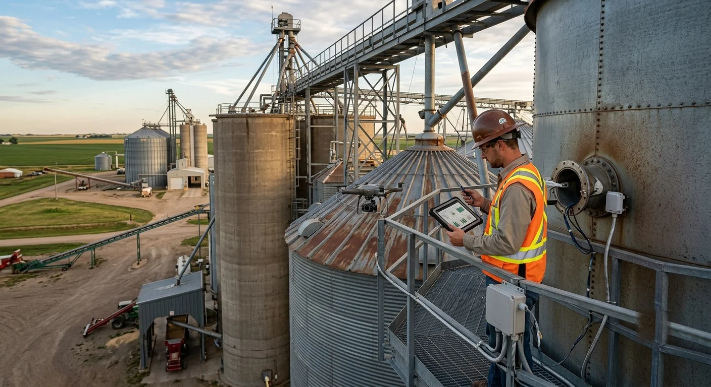
Installation Reality: What a Real Deployment Looks Like
A typical retrofit on an existing site, with six silos and one controller, runs about a day to a day and a half for a competent installer. The work breaks down roughly as follows:
- Mount the sensors. Each sensor mounts on top of the silo, either through an existing inspection hatch or through a small flange welded onto the roof. The sensor sits off-centre from the fill point, ideally about one-third of the silo radius from the wall. This is where most “the readings are weird” problems come from. Get the mounting position right and the rest is easy.
- Run the RS485 cable. Shielded twisted-pair, routed through conduit, away from any high-current lines. Daisy-chain the sensors on the bus and terminate at the controller.
- Mount and power the controller. Wall-mounted in a junction box near the silo cluster, powered from 12-24V DC. Cellular antenna mounted with a clear line of sight to the sky.
- Commission the sensors. Each sensor runs a one-time “learn” cycle to identify and suppress false echoes from internal structures (ladders, support beams). This takes a few minutes per sensor.
- Configure the dashboard. Enter each silo’s dimensions, label every silo by what is inside it, set the alert thresholds, invite the people who will receive notifications.
After that, the system runs. Maintenance on the sensors is essentially nil for five to seven years. The controller takes a remote firmware update once a year. The cellular SIM renews automatically. The only routine task is a visual check on the antenna face once a year, which usually shows no buildup.
When a Monitoring System Pays Back
The financial case for silo monitoring is unusually clear. The savings fall into four categories:
- Working capital released by lower buffer stock. Most sites without monitoring run high buffer stock as insurance against running out. With reliable continuous readings, the buffer can be cut significantly, freeing capital tied up in feed or grain that does not need to sit on site.
- Emergency deliveries avoided. Each emergency delivery costs meaningfully more than a scheduled one, in both freight premium and the time spent chasing suppliers on short notice. One avoided emergency per year often covers the system cost.
- Overfill incidents prevented. A single overfill that damages a fill pipe or a pressure relief vent can cost more than the entire monitoring system, before counting the wasted product on the ground.
- Operator time recovered. Time spent climbing, knocking, and recording becomes time spent on something more valuable. On a busy mill this adds up faster than people expect.
We avoid quoting specific payback periods because they vary widely by operation size and material value. In practice, on sites we have deployed, the payback question stops coming up after the first stockout avoided or first overfill prevented.
What to Look for When Choosing a System
A few questions cut through most of the noise:
- Is the sensor right for the material and environment? Radar for dust, radar for outdoor, radar for low-dielectric powders. Ultrasonic only for liquids in clean indoor environments. This decision determines everything downstream.
- Does the controller support enough sensors per unit? Eight RS485 sensors per controller covers most farms and feed mills with one unit. More sensors per controller is rarely useful; fewer becomes expensive at scale.
- Is the connectivity cellular by default? Cellular is the safest default. LoRaWAN is an option to keep open for sites that grow into it, but should not be the only option a controller supports.
- Does the dashboard surface the right information without configuration? Per-silo tiles, trend graphs, predicted empty date, alerts, and delivery logging should all be there on day one, not behind a configuration project.
- Is there an API? If the system cannot feed an ERP or feed planner, it will eventually be replaced by one that can. The API is what makes the system durable.
- What happens when a sensor goes offline? A good system raises a “sensor unreachable” alert within an hour, not silently shows the last-known reading. Quiet failures are worse than no system.
Where to Start
If you are running an operation today without continuous silo monitoring, the practical first step is to instrument your most critical silo. The one whose stockout would cost the most, or whose overfill would damage the most. Prove the value on that single silo for a quarter, then expand to the rest of the site.
The Agrinovo 80 GHz radar level sensor and the Omni Exodus Controller are designed to work together out of the box, and the cloud dashboard is the same whether you start with one silo or a hundred. The system grows with you. Start small, get the value, expand from there.
For a deeper dive into the underlying sensor choice, see our silo level sensor comparison guide. For the full deployment architecture, see our IoT silo monitoring solution page.